- sales.hk@pfc-device.com
- 852-2558-0181
Application Note
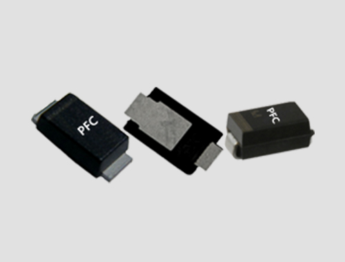
SMAF-A
PFC new development patterns SMAF-A package product for mobile phone charger and power supply applications Network & Communction need to develo...
PFC new development patterns SMAF-A package product for mobile phone charger and power supply applications Network & Communction need to develo...